POTS Adapter
Quick Start Guide
This guide is intended for professional installers and Peplink Certified Partners. If you are an end user, please contact your service provider for installation assistance.
POTS Adapter Setup
Step 1. Locate and Mount the POTS Adapter
-
Choose a safe and secure location that also provides sufficient room for the installation of cellular antennas and running of cables.
-
Place the POTS Adapter antennas ideally away from large metal objects which may block the signal.
-
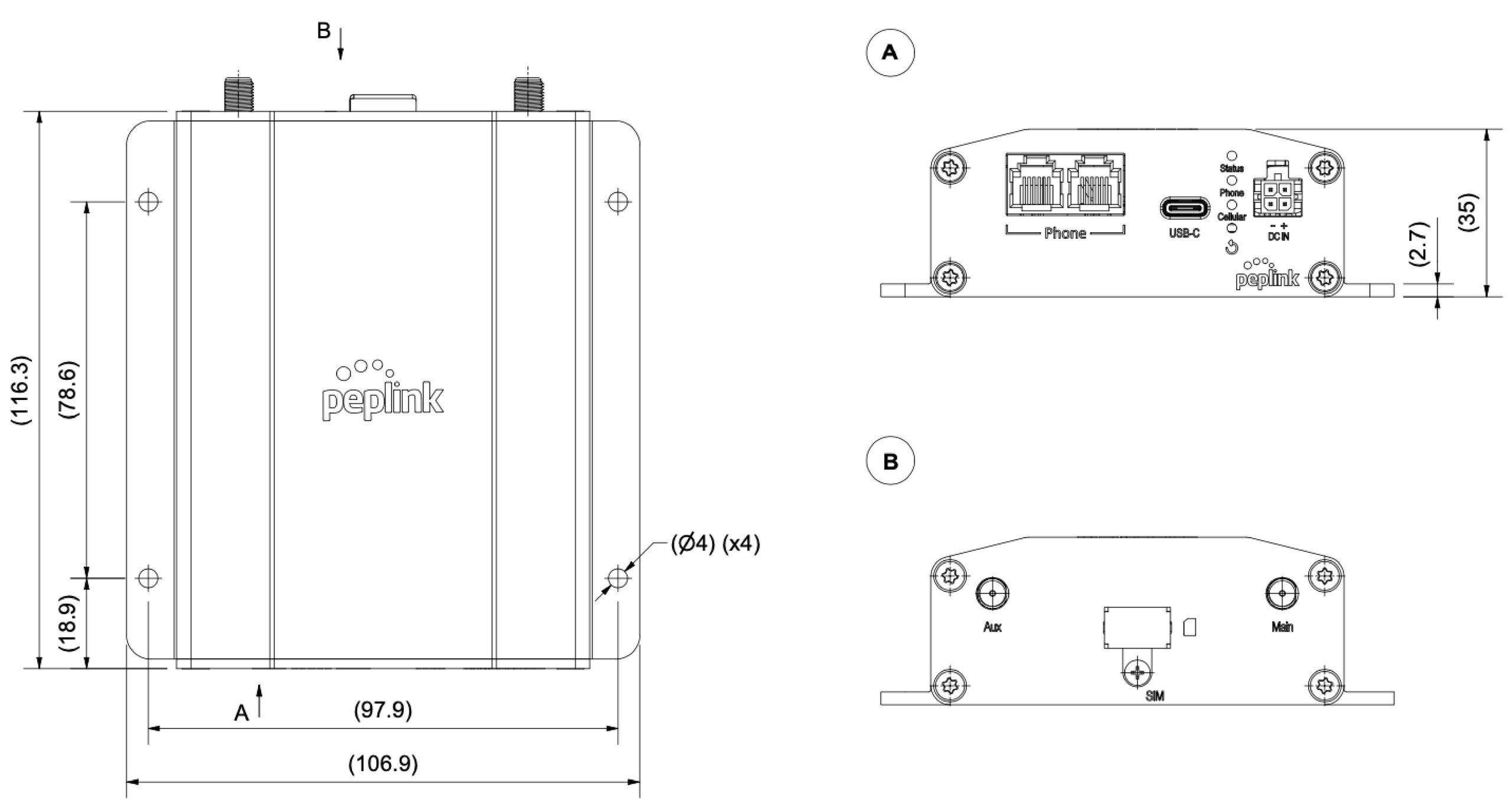
Securely mount the unit after identifying the location, the POTS Adapter can be fixed to a surface by fastening up to 4 screws through the holes on its integrated flange mount. 1
1 Please refer to the technical drawing below for the hole position details and other related dimension.
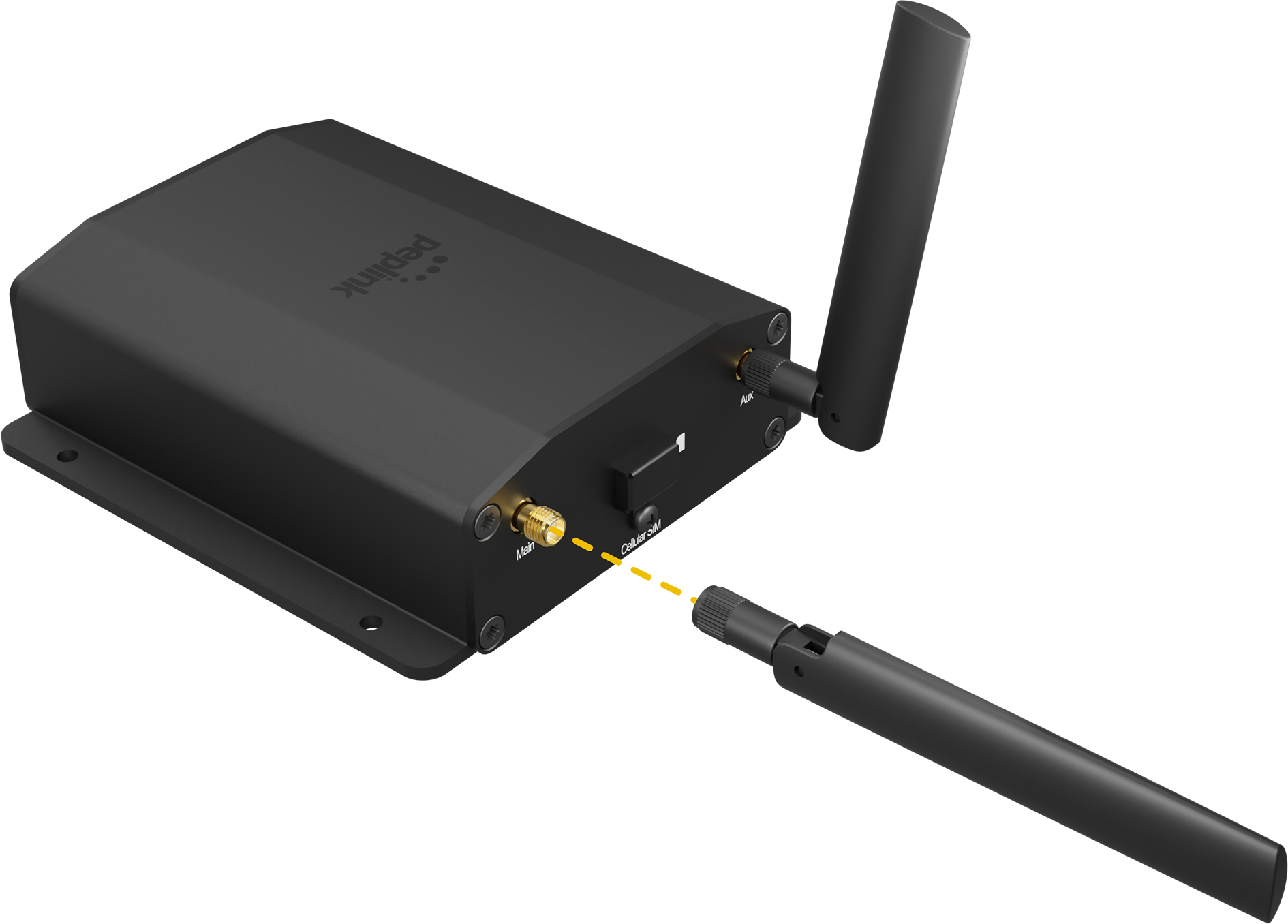
Step 2. Antenna Installation 2
-
Attach the two LTE antennas to the POTS Adapter.
-
Place the antennas perpendicular to the ground, pointing straight up.
2 If required, install Peplink’s Mobility Antennas with an extension cable and position antenna to get a better signal strength.
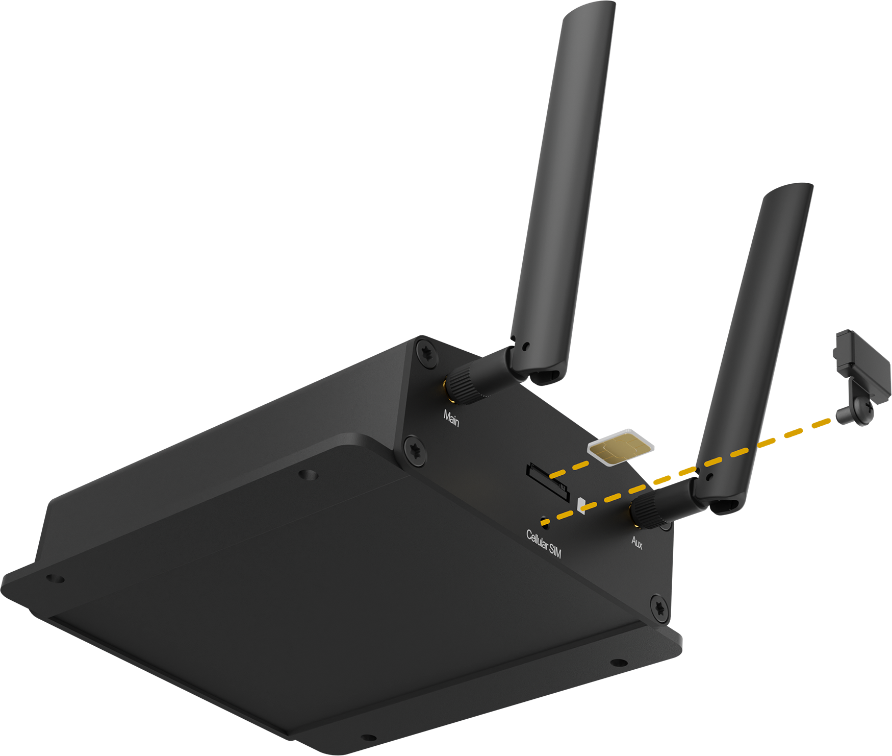
Step 3. Physical SIM Installation
-
Untighten the screw of the SIM cover.
-
Insert the physical SIM into the slot.
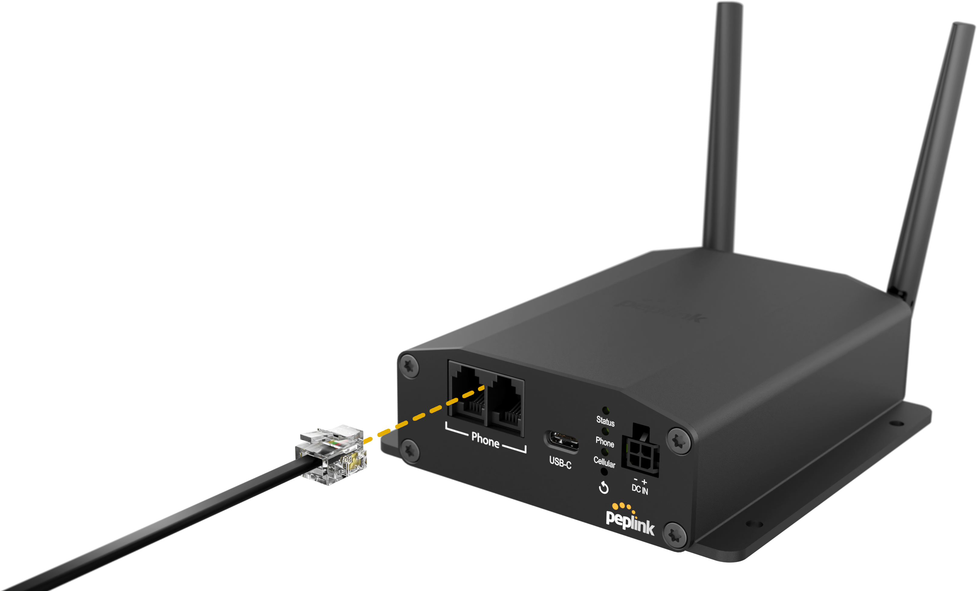
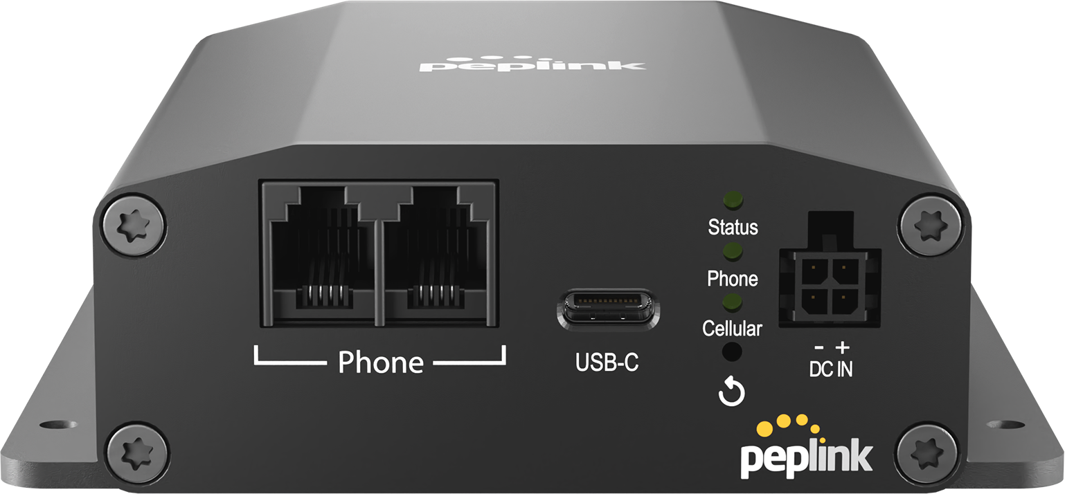
Step 4. Establish a Phone Line Connection
-
To connect your “dialer” equipment 3 to the POTS Adapter, it requires a cable with an RJ11 connector at one end and another connector that is compatible with the “dialer” equipment at the other end.
-
Plug the RJ11 connector into the “phone” port on the POTS Adapter. This allows the “dialer” equipment to communicate through the phone line service over VoLTE.
3 A “dialer” equipment refers to all standard POTS equipment which includes but is not limited to fire alarm control panels(FACP), security system alarm panels, elevator emergency phones, gate access phones or intercoms, fax machines, and office telephones.
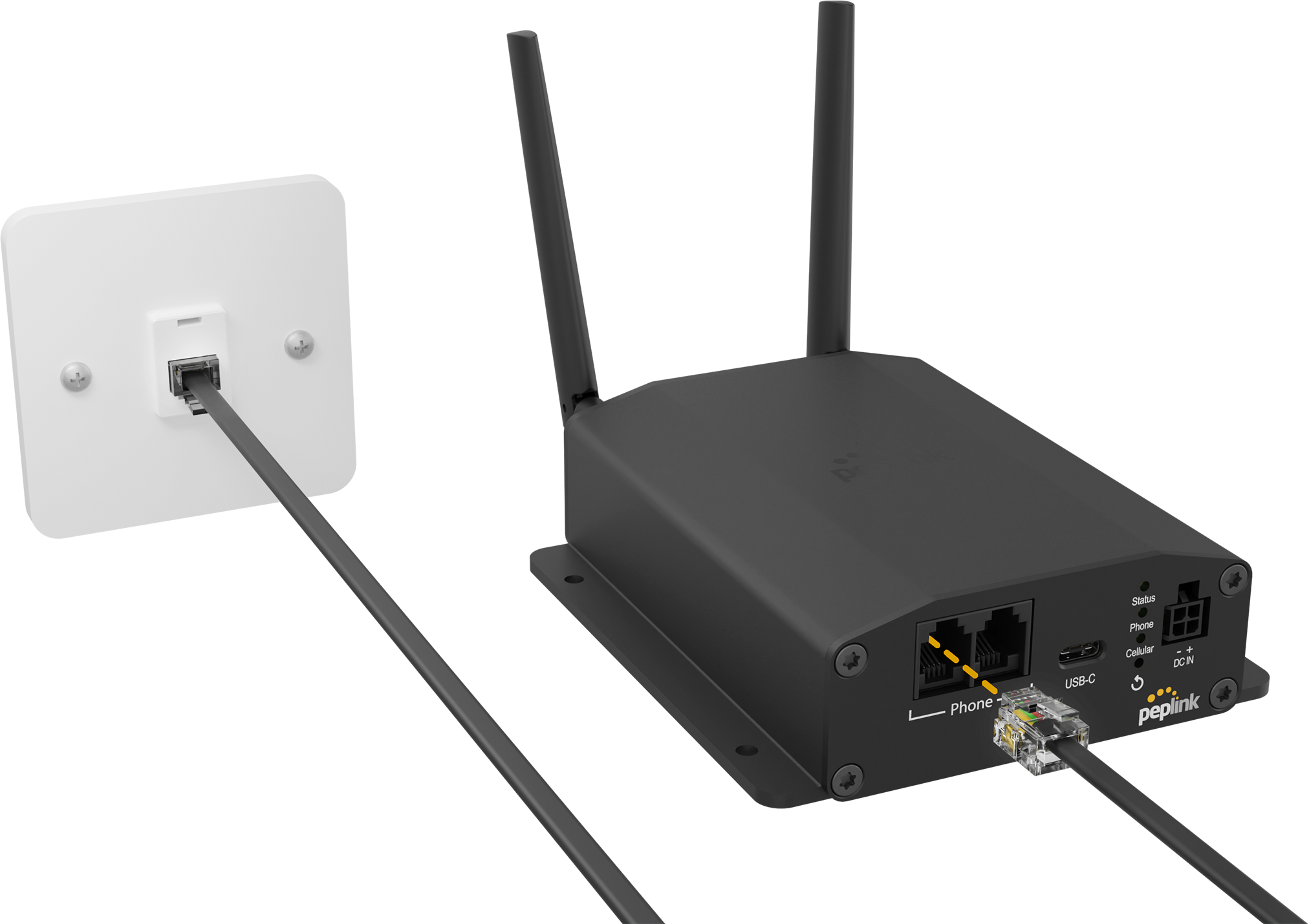
Warning: Do not connect the RJ-11 phone port of the POTS adapter directly from the wall jack with active voltage. This will damage the device permanently. The “phone” port is only to be connected to a phone device or main console.
Step 5. Power Connection
-
POTS Adapter can be powered up with a single source of a 4-Pin Micro-Fit Connector or a USB-C (5V@1A) power supply.
-
In case of an unforeseen power outage, a dual power setup is recommended for redundancy.
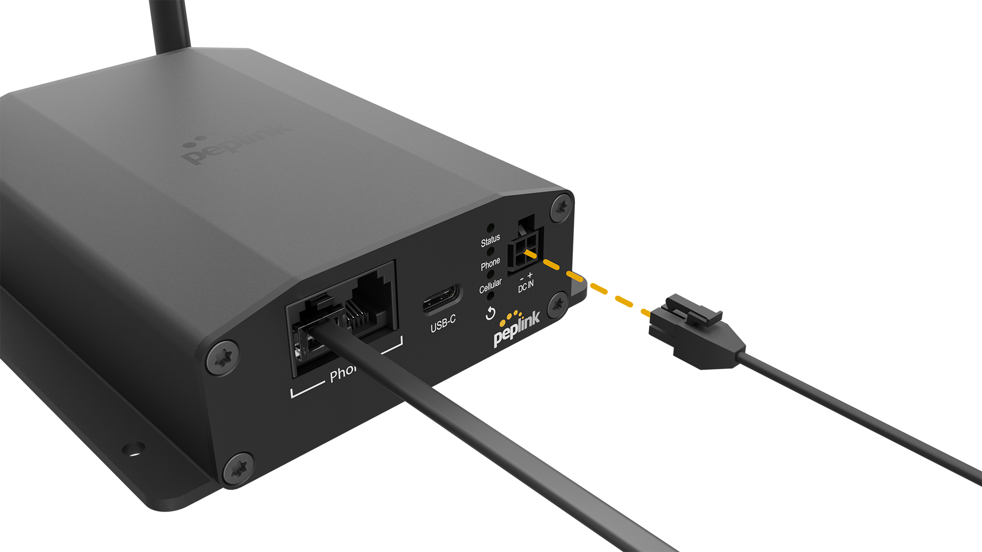
Micro-Fit
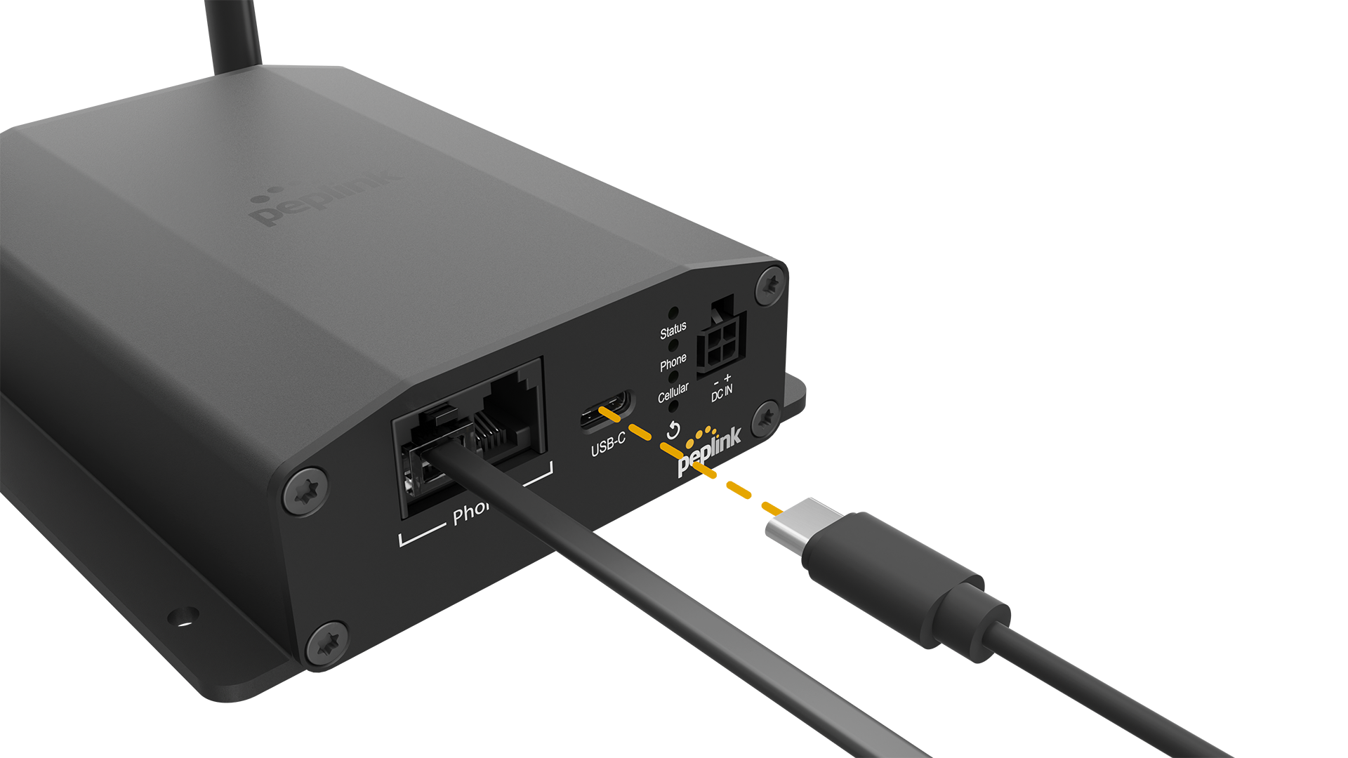
USB-C
Step 6. Configure the POTS Adapter
-
Connect the POTS Adapter to a device accessible to the WEB configuration UI via the USB-C interface4.
-
Enter https://192.168.50.1 as the URL of a browser. A login page will pop up.
-
Log in to the router with the following information.
Default username: admin
Default password: admin -
Follow the guide and change the login password.
-
Modem settings can be configured in the Web-Admin interface as required. For detailed instructions, please refer to the user manual.
4 The POTS Adapter utilizes the Remote Network Driver Interface Specification (RNDIS) to establish a connection with the WEB-based user interface. The RNDIS driver creates a virtual Ethernet link on your computer. Ensure that the RNDIS driver is installed on your computer. Please note that the RNDIS driver is available for Windows OS and Linux OS only. MacOS is not supported.
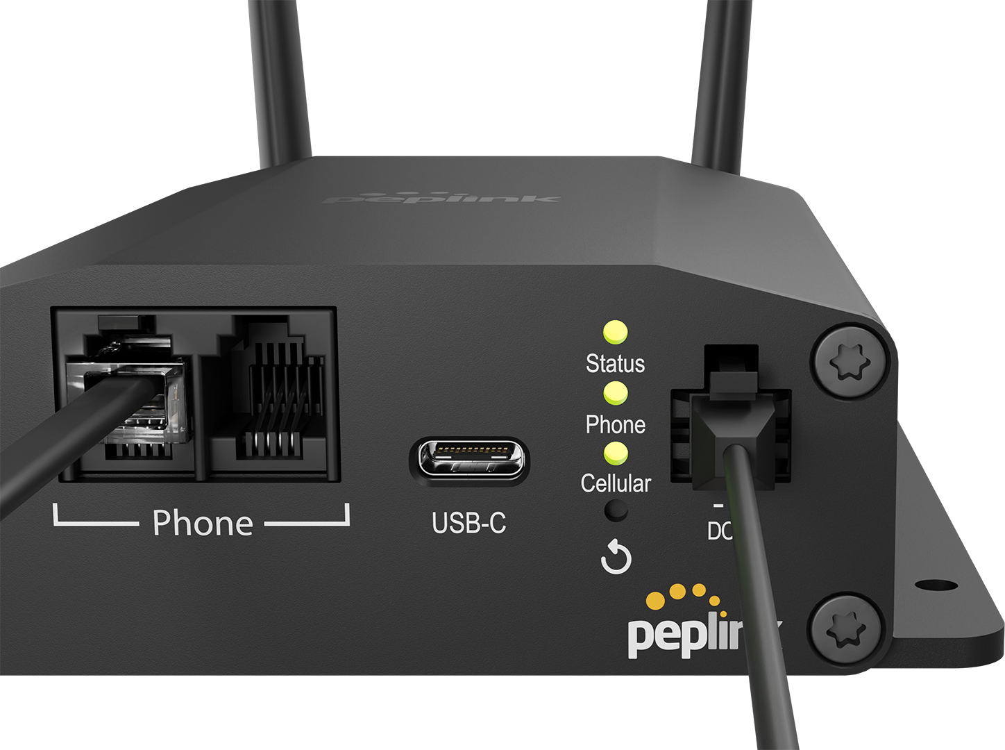
Step 7. Check the LEDs Indication 5
-
Once the device is booted up, the “Status” light will turn steady green.
-
Once the device is connected to the network, the “Cellular” light will turn steady green.
-
Once the device is registered successfully and ready for a call, the “Phone” light will turn steady green.
-
When all three green lights are steadily on, the device will now be ready for use.
5 Please check POTS Adapter User Manual for detailed LEDs behaviors.